Friday 29 November 2013

Ibanez RG870 - adding an internal Roland pickup

Having added a Roland GT3 pickup kit to an Epiphone SG and been happy with it for quite a while I decided to get myself a more advanced guitar. The selection criteria were 24 frets , a locking tremolo and sufficient room behind the bridge pickup to fit the Roland hex pickup.  I knew I'd probably be looking for a "metal" orientated guitar and after a lot of trying out guitars in Denmark Street in London and then GuitarGuitar in Epsom I settled on an Ibanez RG. The one I really like has the flamed top but I didn't want to spend that sort of money if it then proved very difficult to install the GT3. I had a look on eBay and found a metallic blue one that eventually I won for about half the new price. When it arrived it really was as described - it looks completely unplayed with no blemishes or scratches at all and in a very nice semi-rigid case.


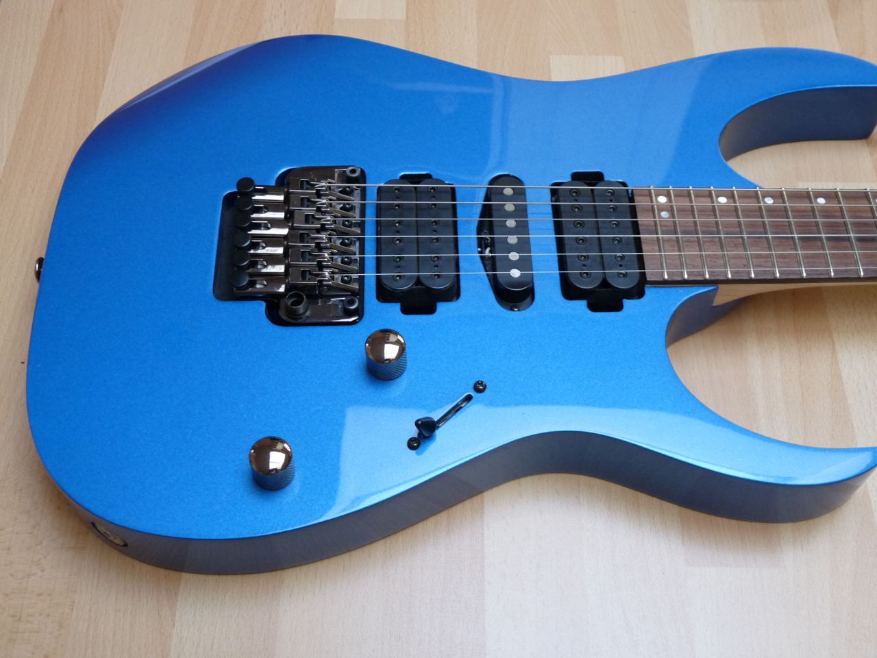
Original Ibanez RG870
First thing to do was remove the neck and all the hardware to leave just the body. Next I removed the backplates to see what options there were for installing the various parts of the GT3 kit and take some photos so that if something gets disconnected you know where it goes back to.

Ibanez RG870 Cavities
My first impression was "this doesn't look very encouraging" as the cavities looked too small but after a bit of thinking I came to realise that because of the jack socket cavity size it could actually be quite a simple installation with no need to rout new body cavities. I carefully measured the various components and did a rough sketch to confirm how big the cutout for the  "output" plate would need to be.


Working out the output plate dimensions
I realised that it would be possible to mount the 13 pin and jack sockets adjacent to each other on one plate. (The jack socket pictured here is the one that comes fitted to the RG. I had intended to re-use it but in the end it proved too long. More of that later). 

This next operation took the longest of all, not because it's particularly difficult, but because I had to pluck up the courage to attack my new guitar with a router. To ensure the router went where it was supposed to go I decided that some form of guide was essential. I marked out and cut two sides from MDF and joined them together using thin plywood which had an  opening of the required size cut into it. I then protected the guitar body with masking tape  before clamping the guide into position.


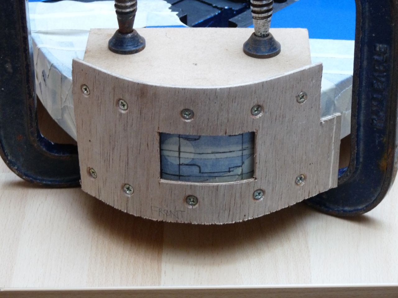
Router guide clamped in position
Once I had made the first router cut I found that it was actually a lot easier than I thought it would be and that the guide very effectively prevented any overcut. I reckon the final result isn't bad for a first attempt. For the plate itself I used some scratchplate material that I had bought for another project. Once cut to the right dimensions I immersed it in boiling water that softened it enough to allow it to bend to the shape of the guitar.


Rout for plate completed and plate bent to shape
The hole through to the cavity can then be cut. I kept the router guide in place and used a jigsaw to make the opening. I then drilled the holes in the output plate to make sure that the two sockets would fit correctly. It was at this point that I realised that if I made the plate slightly larger it would make fitting the various wires much easier so I went through the whole process again to accommodate another 8mm on the plate.


Hole cut through to cavity
One last thing to do before starting to try out component fit was to drill a larger hole between the main cavity and the jack socket cavity. There are a lot of cables/connectors that need to pass though here so I ended up enlarging the existing hole to 12mm.


Two multiways go to the sockets + wiring to jack socket and switches
Next it was time for the bit which, in hindsight, I found the most difficult, drilling holes without damaging the guitar's paintwork. I thought that simply protecting the surface with the masking tape would be sufficient but the finish still chipped away. In the end I resorted to marking out the holes onto MDF first and then clamping this to the body and drilling though it. Better than masking tape but still not perfect. Luckily the flanges on the switches cover the worst of the damage. (My fallback position if the paintwork really did finish up looking bad would have been to fit a scratchplate over the offending area)

Because Ibanez had already provided a nice, wide cavity for the jack socket it was possible to fit both the up/down push switches and the output select toggle into the existing space. Having drilled the holes, I inserted the switches in their respective positions and then tried fitting the plate with the two sockets on. It was at this point that I realised the original Ibanez jack socket was clashing with the selector switch. A quick search in my spares box found a much shorter socket and I used this instead. 

Time to get the soldering iron out and make the common connections between the switches and then the lead to the jack socket. This proved quite tricky. You will need a soldering iron with a fine tip and a steady hand. The rest of the wiring can then be threaded through the hole between the cavities, the final connections to the selector switch soldered and multi-pin connectors snapped into place.  There's also the synth volume control to be added into the main cavity and plugged into the PCB.


Synth/Guitar selector switch wiring
Main cavity wiring
Before doing anything else I plugged the guitar into my GR-55 to check that the switches were working correctly. All was OK so the conventional pickups could be refitted, having first taken the Roland pickup lead through the pickup cavity and into the main cavity. I didn't want to permanently fix it at this stage as I needed to restring the guitar to check clearances.

The wood between the rear humbucker cavity and the rout for the tremolo system is 8mm, exactly the same as the pickup. Once I'd  refitted the tremolo block and restrung I found that the pickup could be screwed directly to the guitar body without any need for packing but I think I may need to review this once I'm properly set up. Looks like I might need to bring the  pickup up a few mil.


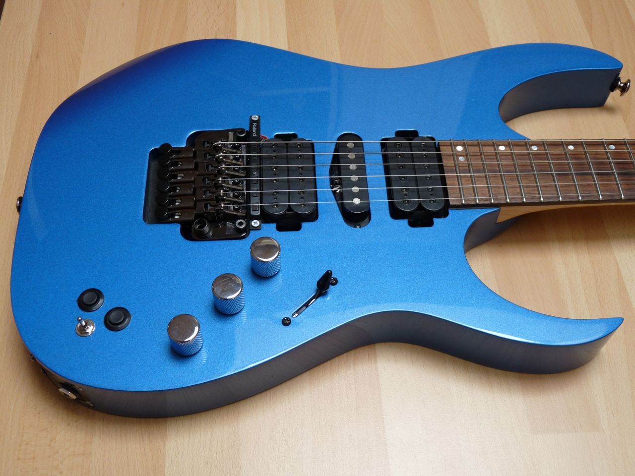
Here's the completed project.


The finished Ibanez RG870
A few finishing touches are still needed. The edges of the routed hole need painting black, as do any silver coloured screws and the three, large chromed control knobs need to be replaced with original Ibanez ones (once I can get hold of a third knob for the synthesiser volume) as they are too large. I'm toying with adding an LED but not until I've worked out how to drill holes without damaging the finish.


In many ways the RG870 has proved to be the ideal guitar for adding the Roland pickup to. It has not required any additional cavities to be routed and therefore no new backplates. The existing jack socket cavity is large enough for installing the switches and there is just the right amount of space for the new pickup. The main cavity has plenty of room for the additional volume control and the Roland PCB just fits in.

I'm pleased with how this project has worked out. If I can crack the hole drilling problem then I might just treat myself to the flame topped RG870 that I saw in the guitar showroom.

RG870's in GuitarGuitar, Epsom
If you have any questions, want some specific dimensions or advice please contact me. For general information about vguitars, guitar synthesisers etc. then join the best forum around - http://www.vguitarforums.com

No comments:

Post a Comment